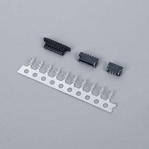
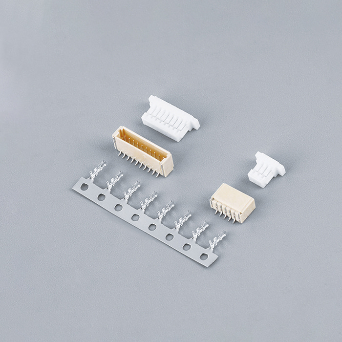
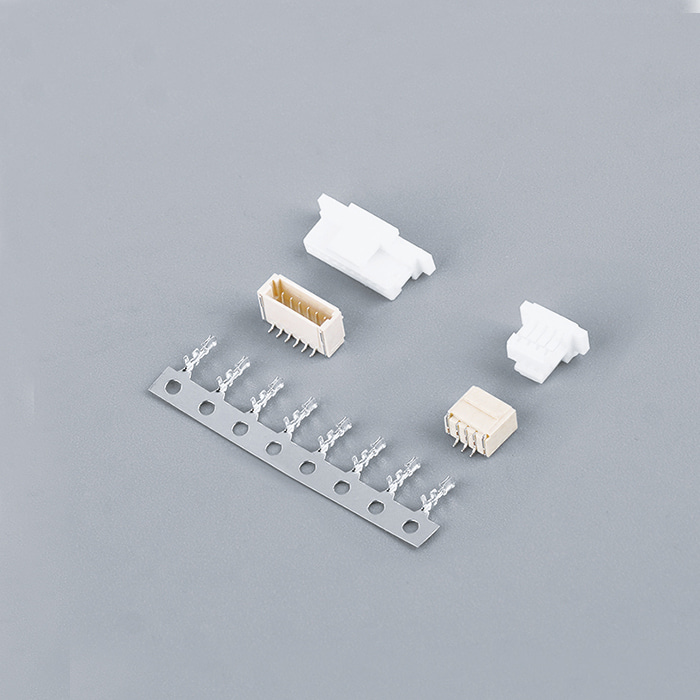
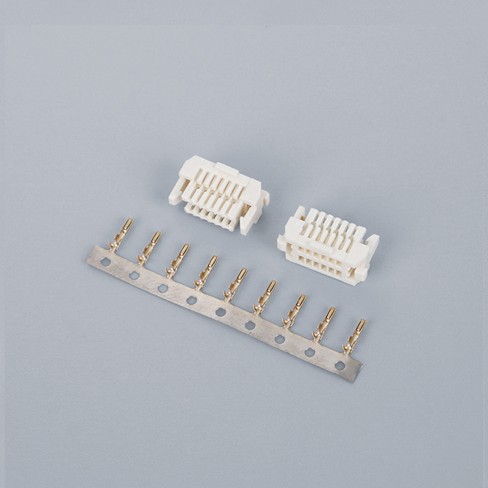
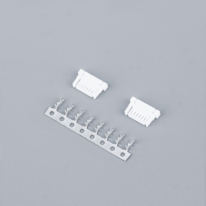
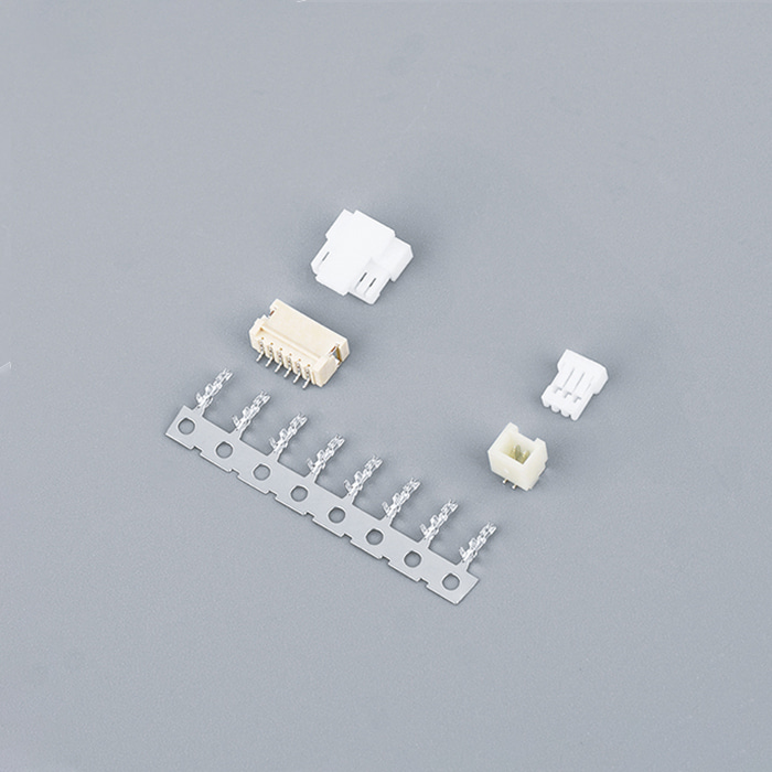
A question that regularly shows up across electronics discussion boards, maker forums, and professional design sites is how to correctly match conductor size with connector specifications. Designers and technicians often need to connect flexible wiring harnesses to printed circuit boards using Wire To Board Connectors, and choosing the wrong wire size can cause poor mechanical engagement, higher resistance, or even premature failure. People working on custom harnesses frequently point out that connectors themselves are just one part of the challenge — the conductor’s diameter and insulation thickness also play a critical role in the overall connection quality.
Similarly, engineers and assembler teams often discuss issues related to Wire To Board Crimp Style Connectors where improper pairing between terminal, connector housing, and wire can cause unreliable crimps or difficulties during assembly. These challenges aren’t just theory — they appear repeatedly in community troubleshooting threads and design guidance where professionals share common pitfalls and better practices.
Why Wire Size Matters in Connector Design
At its core, a Wire To Board Connector creates both an electrical and mechanical pathway between a free-moving conductor and a rigid printed circuit board. When the wire gauge doesn’t properly match the connector’s terminal design or the crimp profile, several issues emerge:
If the conductor is too small compared with the terminal’s crimp barrel, there isn’t enough metal-to-metal contact. This may cause poor strain relief and eventual separation under vibration or mechanical stress.
A mismatched wire gauge could increase contact resistance, especially in power applications. Elevated resistance not only reduces efficiency but can also generate heat inside the connection joint, which degrades insulation over time.
Some designs require a precise conductor thickness to form a secure, gas-tight connection in Wire To Board Crimp Style Connectors. A conductor that’s too thick won’t sit deeply enough in the terminal, resulting in incomplete crimp deformation. Too thin, and the crimp may not grip the conductor strands reliably.
Selecting wire diameter that aligns with published electrical and mechanical specifications is one of the easiest ways to increase assembly success.
How to Determine Wire Gauge Requirements
To match wire size effectively, follow these practical steps:
1. Consult Connector Specifications
Every Wire To Board Connector system has datasheets outlining acceptable wire gauge ranges. These ranges relate directly to the terminal crimp dimensions — if the wire size falls outside this range, the connector won’t function as intended.
2. Consider Current and Thermal Load
Larger conductors carry more current. Even if a smaller wire fits mechanically, it may not support the current requirements without excessive heating. For higher-current systems, always select a wire gauge that meets or exceeds the electrical needs.
3. Account for Insulation Thickness
The insulation adds to the overall wire diameter and affects how the terminal’s insulation wings fold during crimping. Too thick insulation may prevent proper insulation crimp closure on Wire To Board Crimp Style Connectors. This can compromise strain relief and permit movement inside the crimp.
When all three factors are considered — mechanical, electrical, and insulation — the connector assembly process becomes far more predictable and reliable.
Tools and Techniques for Matching and Assembly
Matching wire gauge alone isn’t enough without proper tooling and handling techniques. Two aspects are frequently highlighted in electronics assembly forums:
Proper Crimp Tools
Dedicated crimping tools with calibrated dies help form crimps that conform to the conductor size and terminal shape. Ratcheting tools are beneficial because they provide consistent compression through the complete crimp cycle, reducing variance between crimps.
Measurement Aids
Some assembly technicians use simple gauges or calipers to verify wire diameter before crimping. This ensures that the stripped conductor fits squarely within the crimp barrel without excessive gaps or force — a factor frequently discussed as a better practice in industry blogs.
Employing these tools helps avoid common mistakes such as under-crimping (which doesn’t compress the conductor fully) or over-crimping (which can deform conductors and weaken connections).
Wire Flexibility and Mechanical Stress
Another real-world challenge is the effect of mechanical movement on connections. Since wiring often routes through dynamic sections of equipment, the flexibility and gauge of the wire affect how loads transfer to the connector. In assemblies where the wire moves frequently, connectors must absorb motion without fretting or loosening. Some design guides highlight that improperly matched wire and connector systems are more susceptible to motion-induced wear or fretting.
Selecting a conductor that not only fits the connector but also matches the expected movement and vibration profile significantly enhances reliability.
Documenting Connector Selection in Design
Professional designers often maintain detailed documentation of connector choices, including:
Wire gauge selected
Connector family and terminal type
Environmental or mechanical considerations
Tooling and assembly instructions
This documentation helps design teams avoid repeating issues that other developers have encountered, especially in multi-board or complex assemblies where connector interfaces matter for signal integrity and mechanical stability.
Using well-documented specifications and adherence to those criteria during assembly reduces guesswork and improves reproducibility across large production runs.
Practical Tips from Modern Assembly Experience
Users and professionals alike recommend these practical tips:
Match wire gauge exactly as specified in the connector datasheet.
Avoid improvising with wires significantly thicker or thinner than the allowable range.
Conduct basic pull tests and continuity checks after crimping and before final assembly.
Such steps help prevent many common pitfalls that occur during assembly and field operation.



 English
 Español
 Türk
 فارسی